
Duplicator i3 Troubleshooting

-
LCD Infomation
-
Recommended Mods
-
Extra Mods
-
Part Specs
-
Tips
-
Slicer/Host Settings
-
User Mods
-
Troubleshooting
-
Fourms
The Duplicator i3 is based on the revolutionary work of reprap core developer Josef Průša (Prusa).
-
Printer ships with 3000mm (~10 ft.) Black PLA Filament
-
Extruder: New! MK10 Single-Extruder (with Steel X-Carriage)
-
Filament Size: 1.75mm Dedicated
-
Layer Capability: 0.1mm (100 microns)
-
Build Envelope: 200mm x 200mm x 180mm (8in. x 8in. x 7in.)
-
Build Surface: Heated Bed Plate
-
Filament Capabilities: PLA, ABS, NinjaFlex, Nylon, LayWood, LayBrick, CopperFILL, BronzeFILL, MOLDLAY, Conductive, plus more!
-
Compatible Software: Cura (Opensource), Simplify 3D (Details)
-
File Type: Gcode
-
File Transfer: microSD Card & USB
-
Frame Color: Steel Frame (Powder Coated Black)
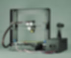
Features:
Amongst the features packed neatly into this platform are an MK10 single extruder with cooling fan, a gcode based micro-controller, and a standard Heated Build Plate. Unlike most other Prusa offerings on the market, this i3 comes standard with a custom electronics housing and a custom filament holder (both in stamped steel). For the value this machine can not be beat. This printer is the ultimate reprap!


Parts Specification:
Controller Board
The Duplicator I3 printer uses the Melzi printer board in the controller box (see Melzi info on RepRapWiki). The stepper drivers are A4988 chips. The board is powered from 12VDC which is then regulated down to 5V by a 7805 linear regulator (DPAK surface mount with heatsink). The power for the SD card is robbed from the FTDI 3.3V power.
Since the SD card is powered by the chip that provides USB communications to the board. When you plug in the card, this causes a tiny power surge that resets the chip, that in turn resets the main processor and causes the firmware to reboot (the beep and fans turning on for a second and if you were paying attention, the LCD display shows the logo- a clear sign that ONLY happens when the firmware reboots). This is normal and expected. A side effect is that the firmware checks the SD card slot on reboot so it kind of auto mounts the card upon card insertion.
-
The I3 uses the Melzi controller board.
Melzi Board
Extruder Information
MK10 Style Replacement Extruder assembly from Uncle Chuck
All Metal Hotend kit from Micro Swiss LLC (formerly AVN Swiss)
Fans
-
Extruder Cooling Fan
-
Connector: 2pin (3pin adaptor included) (We only need 2 wires fans but can use 3 wire fans and ignore the 3rd wire)
-
MTBF: 30,000 Hours
-
Noise: 14.00dBA -Nice quiet fan!!!
-
Airflow: 4.11CFM (Correct airflow of 4.0CFM or better)
-
Rated Voltage: 12V (correct 12V rating)
-
Rated Current: 0.06A (current is a non issue)
-
Dimensions: 40.0 x 40.0 x 10.0 mm (correct same size as original)
-
Filament Cooling Fan
-
Rated Voltage: 12V
-
Dimensions: 30.0 x 30.0 x 10.0 mm
Heated Bed
-
12V MK3 Aluminum heated bed MK3 heated bed from Robotdigg MK3 heated bed from Amazon
-
Material:Aluminum Plate
-
Voltage:12V/24V
-
Max Temperature:180 Degree Celsius
-
Dimensions:214mm x 214mm
-
Thickness:3mm
-
1 Layer 35μm (1oz base) Copper
-
Resistance between 1.4 and 1.6 ohm for the 12V
-
Resistance between 5.0 and 5.4 ohm for the 24V
Repetier Firmware configured for the I3 Melzi Board and LCD
-
Download then unzip the file Wanhao_DupI3_v0923.zip. Open the INO file in the Arduino IDE (known to compile with v1.6.4).
-
You will need to set the board type to Sanguino W/ATmega 1284 16MHz
-
After compiling upload to the board. This is only possible if you have a newer board with the Bootloader on it. If there is no bootloader then you will need an ISP programmer.
Initial Setup
Wanhao I3 Unboxing and Hardware Setup Rev D
Wanhao I3 First Run Experience Manual Rev A
This is the file provided on the SD card shipped with the initial units.
Recommended Tools
These are a list of tool I would recommend to any person that owns a 3d printer. They come in handy all the time when doing mods, repairs or just regular maintenance.
The set screws the rod holders use are an EXTREMELY common size 1.5mm. For sure, you will want to have more than one of these long term.
Also, a ball driver for the M3 and M4 is pretty much the next must have if you get into this hobby.
Here's a list of my favorites L allen wrench set with ball ends on one end. L Wrench Set Ball Ends $10 well spent. These are harder and stronger than most- less likely to strip out and worth every penny
Ball driver set. These make your life a dream when they can be used. I am lost and usually angry when I don't have these handy. Ball Driver Set $16 but trust me, the ease of use factor- you'll NEVER go back or regret these.
Not so much a big deal for this printer since all the factory screws tighten into threaded metal. But long term and even for the mod of using locking M3 nuts on the long Bed leveling screws, this is another must have. M3 nut driver with massive recess for long screws. Again, just doing the bed mod- this pays for itself in one usage. M3 Nut Driver $6 bit again, in the hobby, there are a million M3 nuts, and this is one of my most used tools.
GOOD side cutters. There is a difference, this is one of the best. Side cutters $10, but again, you'll go through 3 pairs of cheap ones that are never as good as this one.
Calibration:
-
Bed Leveling
-
Leveling the Z-Axis
-
X Rod/Carriage Adjustments
-
Filament Steps/mm
-
Extruder/Filament Retreaction Calibration
-
Extruder Heat Manager and PID Tuning
Bed Leveling:
Why Level your bed
Perhaps the answer to this is obvious, but as a newbie I really didn't understand how important this was.
Symptoms If you have the following symptoms then you probably need to level your bed.
-
The initial layer is not sticking to the bed.
-
The initial layer isn't complete; parts of the print just don't get laid down.
-
The head scrapes the bed in some spots (you probably worked this one out for yourself).
-
Plastic gathers around the head during printing of the first or second layer.
-
When printing the second layer the print head is picking up the first layer
These symptoms can also be caused by other problems. But leveling your print bed is the best and easiest spot to start. If you know other symptoms please add them.
Objective
Apart from having a level bed you also need to set the distance between the bed and your nozzle.
Essentially the nozzle needs to 'squash' the plastic against the bed. If you watch the first layer being printed each thread should end up wider than it does during the rest of the print. As a guide the nozzle should be a paper thickness above the bed. With a piece of paper between the nozzle and the bed you should feel the paper drag against the nozzle as you try to pull the paper out.
Prerequisites
-
The print bed material should be absolutely flat.
-
The Y-Axis smooth rods should be leveled to each other.
-
The Y-Axis base plate should make firm contact against the smooth rods on all four contact points (PLA bushings in the case of Prusa). There should be no rocking when pressing the corners.
-
The X-Axis smooth rods should be level across the Y-Axis rods.
-
The Z-Axis Opto/Mechanical switch and flag should be located on the motor side of the X-Axis carriage.
-
A piece of Letter paper (or A4 if you from one of the more under-developed countries ).
Leveling the Print Bed
The process of leveling is fairly straightforward, and does not require any fancy tools. It involves only six (6) easy steps:
-
Stiffen the print bed support screws.
-
Set adequate tension in four (4) springs.
-
Set the tolerance.
-
Level first diagonals.
-
Level second diagonals.
-
Secure hardware.
Stiffen the Print Bed
To stiffen the print bed, tighten the nuts under the bed so that the support screws are absolutely perpendicular to the print bed surface. Nylon-backed nuts insure that the screw will remain set, but if those are not available, LockTite, paint, or nail polish will get the job done. If using these, allow time to set before moving on, as vibrations tend to loosen things up.
Set Spring Tension
This step will depend on if you are printing on the aluminum plate or if you have added a glass plate to your printer. Typically you want to compress the springs almost all the way but then back off a little so there is some give to allow for adjustment during the bed leveling or if the nozzle was to run down into the bed. If you have added glass you may find that you have to compress the springs all the way to keep from having the nozzle hit the glass bed when homing. There is a printable part that can be used to give the Z Endstop some more adjustment with the glass bed Adjustable Z Endstop Link.
If you have your bed set where you know the Z Endstop will hit before the nozzle hits the bed (or glass) you can skip to the next section, otherwise you should adjust the thumbscrews (or wing nuts) until the springs are all the way compressed. That way we know the nozzle will not crash into the bed.
Adjusting the Z-Axis Home Position
Either though the LCD or the Host software Home all the axis. After the Z axis homes the nozzle should be above the bed (glass plate or aluminum bed). If the nozzle is too high and there does not look like there will be enough adjustment in the springs and you are using the adjustable Z Endstop then you will need to adjust the endstop screw so that the screw will be shorter (screw it clockwise).
Tolerances
In addition to being level the distance between the hotend and the bed is important. If you are using a strongly flat bed, such as glass, you should be able to achieve a gap of 0.2 mm. For less flat surfaces your gap will need to be larger. A common method of setting the tolerance is to place a piece of paper onto the bed, so that you can still move the piece of paper, but there is a slight drag.
As you go around the bed, adjusting the level, you should use a piece of paper to check the tolerance.
Leveling Diagonal 1
Disable the Stepper motors in the LCD menu or though the Host software so you can move the extruder and plate by hand.
The leveling order is Front-Left, Back-Right, Back-Left, Front-Right. We refer to the first pair as Diagonal 1. With the Z-Axis homed, and positioned over the Front-Left corner of the print bed, use the tension nut to adjust the height of the print bed. Using the piece of paper between the bed and the nozzle adjust the height until the nozzle touches the paper but you can still pull the paper out with a little bit of drag. Re-home the Z-Axis and checking that the paper still drags. Adjust the nut as needed until you can achieve drag without movement of the print bed.Once you have set the front-left corner, repeat the process with the opposite diagonal corner in the back-right. Return to the front-left corner and verify that nothing has changed. On or two repetitions may be required.
Leveling Diagonal 2
The second diagonal is leveled in the same manner as the first, but starting in the back-left corner, and ending with the front-right. It may be that after completing the procedure to this point, you find that Diagonal 1 is no longer set. It will most likely be a small adjustment, and a second repetition of the leveling process will correct this in most cases.
Reference material from http://reprap.org/wiki/Leveling_the_Print_Bed Content is available under GNU Free Documentation License 1.2
Filament Steps
Calibrating the Extruder Steps/mm or eSteps
Measure 120mm from top of extruder, using some control panel ( repetier host, s3d, mattercontrol ) extrude 100mm of filament:
-
Manual method: Enter the following gcode in the manual gcode box then press enter or send: G1 E100 F3000
-
Or use the Extrude 100mm button on the Host (but make sure your extrusion speed is set to something reasonable like 50mm/s)
-
Now measure the distance from the top of the extruder to the mark you had made. It should be 20mm. If its not,
new_e_steps = old_e_steps * (100 / distance_actually_moved) … or, old_e_steps * (100 / (120 - distance_to_mark))
So now that you have the correct amount of filament being fed....... mostly. Take the new_e_steps and enter that into the Ext1 Steps / mm value in the Printer EEPROM setup from the Host or via the LCD (remember to save the EEPROM if using the LCD).
Repeat the test again to make sure it works and if it is still off do the math over and enter the new value to get even closer.
Video on how to calibrate an extruder
Extruder PID Tuning
The default heat manager for the I3 printer is using the DeadTime method which usually works pretty well. I found that I had to change the PID Gain / Deadtime setting to 3 to get better results without the over an undershooting of the temperatures. The heat manager can be changed to use PID which can yield better results after running the PID Tuning command for a set temperature.Changing to PID and running a PID Tune:
-
Using Repetier Host go into the EEPROM settings and change the Ext1. Heat Manager to 1 and then save the settings
-
With the extruder at room temperature we will need to issue the PID Tuning command. This consists of the Temperature that you want to reach (print at) and the number of cycles of tuning to run. Go to the manual Send GCode box and type in: M303 S220 P5 where Sxxx is the temperature you want to use (200, 210, 220, etc) and Px is the number of cycles to run then press Enter or Send. (note) I have seen some version of the firmware take a C? instead of P? for the number of cycles. If it doesn't like it you can leave it off and it should default to 3 cycles.
-
Once you hit send, the auto tune function will take about 15 minutes to complete. You will see the following information in your log appear multiple times with different numeric values:
-
bias: 103 d: 103 min: 147.98 max: 152.02Ku: 65.06 Tu: 30.67Classic PIDKp: 39.04Ki: 2.55Kd: 149.66
-
Wait until you see the message about PID Tuning being complete or having finished. You will see one last set of numbers.
-
The values you are looking for are Kp, Ki, and Kd. Write these values down, they will be your new PID values. You can use the EEPROM menu to enter these values to the Ext1. P-gain, Ext1. I-gain and Ext1. D-gain (the kp, ki, kd values respectively) or enter the following two lines of code as we did earlier, substituting your experimental values for the ones below:
M301 P39.04 I2.55 D149.66 (press Enter or click Send)M500 (press Enter or click Send)The "M301" command sets the values to the running configuration, and "M500" saves that configuration to EEPROM.
Printer Board Info
Hardware / Controller Board Information.
For settings required when compiling new firmware from source click here
The Duplicator I3 printer uses the Melzi printer board in the controller box (see Reprap Melzi Wiki). The stepper drivers are A4988 chips. The board is powered from 12VDC which is then regulated down to 5V by a 7805 linear regulator (DPAK surface mount with heatsink). The power for the SD card is robbed from the FTDI 3.3V power.
Since the SD card is powered by the chip that provides USB communications to the board. When you plug in the card, this causes a tiny power surge that resets the chip, that in turn resets the main processor and causes the firmware to reboot (the beep and fans turning on for a second and if you were paying attention, the LCD display shows the Wanhao logo- a clear sign that ONLY happens when the firmware reboots). This is normal and expected. A side effect is that the firmware checks the SD card slot on reboot so it kind of auto mounts the card upon card insertion.
LCD Pins / EStop:
There is ONLY the 10 pin LCD connector and the ICSP port.
In the LCD standard in the Reprap community, there is LCD (SPi protocol so at least 3 pins) you go the encoder+ click, so that's 3 more pins, then you got beeper 1 pin, and Estop is a standard in he interface 1 pin. If 2 pins are power and ground, that's all 10 pins accounted for.
The only other connector is the ISCP and that's in parallel with the SD card.
NO in most Repraps, the Estop is just an input to the firmware to reset and there are options on HOW the firmware handles it. NO it is not a power kill, but on some boards it can command a power supply shutdown. Melzi doesn't have any free pins to control a PSU. . This is the low end of the Reprap open source. The Melzi is meant to be a low cost no extra options kind of board. It works, it prints well, but it is NOT every bell and whistle option. That said, it follows standards established in the Reprap community. It runs Reprap firmware. The LCD interface board follows the minimum number of user control inputs- LCD, encoder+click and Estop along with alarm or beeper.

Repetier Firmware EEPROM Settings
These are screenshots of my printers settings as I am currently running it. It seems to be printing very well. I would suggest that you copy down or take pictures of your settings before making any changes. I find it easiest to go into the EEPROM settings from the Repetier Host menu then exit without making changes, then just copy and paste the lines in the log that correspond to the settings into notepad or a text editor.


Converting to the RAMPS-FD Printer Board
These are screenshots of my printers settings as I am currently running it. It seems to be printing very well. I would suggest that you copy down or take pictures of your settings before making any changes. I find it easiest to go into the EEPROM settings from the Repetier Host menu then exit without making changes, then just copy and paste the lines in the log that correspond to the settings into notepad or a text editor.
RAMPS-FD Conversion
Melzi to RAMPS-FD Conversion
This guide will help explain the steps required to convert from using the Melzi controller board to a 32bit processor RAMPS-FD board. More information on the RAMPS-FD board can be found on the Reprap Wiki
Some features of the RAMPS-FD board are:
-
Faster 32bit processor vs 8bit
-
More flash / code space for firmware improvements
-
Faster steps / mm without switching to step doubling or quad stepping because of interrupt constraints
Part 1.
Getting the right parts..
-
Printer Controller Board:(ramps-fd)Geetech Ramps-FD Controller Shield
-
EEPROM for Firmware setting storage:I2C EEPROM Board
-
Stepper Drivers:(You will need at least 4 DRV8825)DRV8825 Stepper Drivers / Carrier board
-
Stepper driver trimpot adjustment ceramic screwdriver:Ceramic screwdriver from e3d-online
-
Stepper Driver Heatsinks:Aluminum Heatsink or:Copper Heatsink
-
heatsink thermal adhesive:Heatsink Thermal Adhesive
-
Arduino Due:Arduino Due board information
-
processor heatsinks:\\(I used 4 on my due atmega chip and 1 on my ramps-fd processor chip)Cosmos Copper Cooling Heatsinks
-
LCD Smart controller:(there are many to choose from)Reprap LCD Smart Controller
-
LCD Smart controller adapter:(for ramps-fd)Ramps-FD LCD Adapter
-
connectors:(for end stops and temp sensors and fans)
-
connectors:(for stepper motors and eeprom)
-
usb interface cable:(any micro usb to usb cable will do)Micro USB to USB Male Cable
-
optional printable ramps-fd enclosure:(you might want to print this while you wait for your parts to arrive)Printable Ramps-fd Enclosure by Delukart